Introduction to Component Visualizers
Unreal Engine’s Component Visualizers offer developers a powerful way to visualize and edit non-rendering component data in the editor viewport. They provide real-time, interactive feedback that helps in creating more efficient and accurate designs, while reducing the time and effort spent on debugging.
Purpose and Advantages of Component Visualizers
Component visualizers are specifically designed to enhance the development process by offering a visually intuitive way to work with non-rendering components in Unreal Engine. Some of the advantages they provide are:
- Real-time Visualization: With component visualizers, developers can see and manipulate their data structures directly in the editor viewport, offering a faster and more efficient way to debug and refine components.
- Interactive Editing: Component visualizers support interactive editing, allowing developers to right-click for a context menu, capture mouse input, and create keyboard commands to modify the visualization.
- Reduced Complexity: By using component visualizers, developers can streamline their code and reduce memory usage. Instead of creating separate components for each piece of data, component visualizers allow developers to visualize and edit lightweight data structures directly.
Real-world Examples and Use-cases
To better understand the power of component visualizers, let’s take a look at two practical examples:
- Spline Component: The spline component in Unreal Engine is a great example of component visualizers in action. When a developer selects a spline, the path, points, and handles are all visualized and interactive, allowing for efficient editing and manipulation of the spline.
- Spot Light Component: The already existing spotlight component that comes with Unreal Engine uses component visualizers to draw the light cones based on the light radius as well as drawing the Light Profile using a LightProfileVisualizer
In conclusion, component visualizers are an invaluable tool for developers working with non-rendering components in Unreal Engine. They offer a real-time, interactive way to visualize and edit data structures, streamlining the development process and enhancing the efficiency of game design.
Setting Up the Environment
Before you can harness the power of component visualizers, you need to set up your development environment by creating an editor module for your game. This process separates the editor-only functionality from your game module, reducing the size of your cooked game and preventing linking errors when the editor module isn’t included.
Creating an Editor Module for Your Game
Follow these steps to create an editor module for your game:
- Visit the Creating an Editor Module page and follow the instructions provided to create an editor module for your game project.
- After successfully setting up the editor module, return to your project and ensure everything is working correctly.
Adding Component Visualizers Module to Dependencies
Once your editor module is up and running, you need to add the Component Visualizers module to the dependencies in your Build.cs file. This ensures that your project can access the component visualizer features.
To do this, follow these steps:
- Open the Build.cs file in your game’s editor module.
- Add the “ComponentVisualizers” module to the PrivateDependencyModuleNames list. Your code should look like this:
PrivateDependencyModuleNames.AddRange(
    new string[]
    {
        "UnrealEd",
        // Other dependencies here
        "ComponentVisualizers"
    }
);
With the editor module set up and the Component Visualizers module added to the dependencies, your environment is now ready for creating and using component visualizers in Unreal Engine. In the next sections, we’ll delve into the process of creating a custom component visualizer and exploring the powerful visualization features it offers.
Creating a Custom Component Visualizer
With the environment set up, you can now create a custom component visualizer tailored to your needs. In this section, we will guide you through the process of creating a new component visualizer by extending the FComponentVisualizer class and implementing the appropriate visualization functions.
Overview of the FComponentVisualizer Class
The FComponentVisualizer class serves as the base class for creating custom component visualizers in Unreal Engine. To create a new visualizer, you will need to derive a new class from FComponentVisualizer and override either the DrawVisualization or DrawVisualizationHUD functions, depending on whether the visualization should render inside the scene or on the editor’s viewport.
class MyCustomVisualizer : public FComponentVisualizer
{
public:
    // Override DrawVisualization or DrawVisualizationHUD depending on your needs
    virtual void DrawVisualization(const UActorComponent* Component, const FSceneView* View, FPrimitiveDrawInterface* PDI) override;
    // Or:
    // virtual void DrawVisualizationHUD(const UActorComponent* Component, const FSceneView* View, FCanvas* Canvas) override;
};
Implementing the Visualization Functions
When creating your custom component visualizer, you will need to implement either the DrawVisualization or DrawVisualizationHUD function to render the visualization in the scene or the editor’s viewport, respectively.
For example, let’s assume you want to draw a simple sphere in the scene for your custom visualizer. You would implement the DrawVisualization function like this:
void MyCustomVisualizer::DrawVisualization(const UActorComponent* Component, const FSceneView* View, FPrimitiveDrawInterface* PDI)
{
    const USphereComponent* SphereComponent = Cast(Component);
	  if (SphereComponent)
	  {
		  const FVector SphereLocation = SphereComponent->GetComponentLocation();
		  const float SphereRadius = SphereComponent->GetScaledSphereRadius();
		  const FColor SphereColor = FColor::Yellow;

		  // Draw the sphere visualization
		  DrawWireSphere(PDI, SphereLocation, SphereColor, SphereRadius, 16, SDPG_World);
	  }
}
In the example above, we first cast the UActorComponent pointer to our desired component type (USphereComponent). Next, we retrieve the sphere’s location and radius, set a color for the sphere visualization, and finally draw the sphere using the DrawSphere function from the FPrimitiveDrawInterface (PDI).
With your custom component visualizer class implemented, you can proceed to the next step of registering and unregistering the component visualizer within the editor module, as discussed in the following section.
Registering and Unregistering the Component Visualizer
After creating a custom component visualizer, it’s essential to register and unregister it with Unreal Engine’s editor module. This ensures that the engine knows when to use your custom visualizer when an actor with the specified component is selected. In this section, we will walk you through the process of registering and unregistering your custom component visualizer.
Registering the Component Visualizer
To register your custom component visualizer, follow these steps:
- In your editor module’s StartupModule function, create a shareable instance of your custom visualizer. This shared instance will be used for all instances of your custom component:
TSharedPtr Visualizer = MakeShareable(new MyCustomVisualizer());- Register the shared instance of your custom visualizer with the engine by calling the RegisterComponentVisualizer function:
GUnrealEd->RegisterComponentVisualizer(USphereComponent::StaticClass()->GetFName(), Visualizer);In this example, we register our MyCustomVisualizer with the USphereComponent class. Replace USphereComponent with the component class you want to visualize.
Unregistering the Component Visualizer
Similarly, when shutting down the editor module, you should unregister your custom component visualizer to prevent any issues. In your editor module’s ShutdownModule function, call the UnregisterComponentVisualizer function:
GUnrealEd->UnregisterComponentVisualizer(USphereComponent::StaticClass()->GetFName());Again, replace USphereComponent with the component class you have registered your custom visualizer with.
Complete Setup on the Editor Module
Here’s a complete example of how to register and unregister your custom component visualizer within your editor module:
class FMyGameEditorModule : public IModuleInterface
{
public:
    virtual void StartupModule() override
    {
        TSharedPtr Visualizer = MakeShareable(new MyCustomVisualizer());
        GUnrealEd->RegisterComponentVisualizer(USphereComponent::StaticClass()->GetFName(), Visualizer);
    }

    virtual void ShutdownModule() override
    {
        GUnrealEd->UnregisterComponentVisualizer(USphereComponent::StaticClass()->GetFName());
    }
};
With your custom component visualizer registered and unregistered within the editor module, you should now be able to visualize the specified component when selecting an actor containing it in the editor. This powerful tool allows for more efficient and intuitive editing of your game assets within the Unreal Engine editor.
Primitive Drawing Functions and Examples
When creating custom component visualizers, you will use a set of primitive drawing functions to visualize and interact with your components. These functions are provided by the FPrimitiveDrawInterface (PDI) and allow you to render various shapes and lines within the Unreal Editor. In this section, we will explore some common primitive drawing functions and provide examples to help you understand their usage.
Common Primitive Drawing Functions
The FPrimitiveDrawInterface offers various primitive drawing functions for rendering lines, points, spheres, and other shapes. Some of the most common functions include:
- DrawPoint: Draws a point at a specified location with a given color.
- DrawLine: Draws a line between two points with a specified color.
- DrawTranslucentLine: Draws a translucent line between two points with a specified color and thickness.
- DrawSphere: Draws a wireframe sphere with a given center, radii, segments, and color.
- DrawBox: Draws a wireframe box with a given center, extent, and color.
- DrawCylinder: Draws a wireframe cylinder with a specified start and end point, radius, segments, and color.
Examples of Primitive Drawing Functions
Here are a few examples demonstrating the use of some common primitive drawing functions:
DrawPoint Example:
FVector PointLocation(0.0f, 0.0f, 100.0f);
FColor PointColor = FColor::Red;
float PointSize = 5.0f;
PDI->DrawPoint(PointLocation, PointColor, PointSize, SDPG_World);
This example draws a red point at the location (0, 0, 100) with a size of 5 units.
DrawLine Example:
FVector LineStart(0.0f, 0.0f, 100.0f);
FVector LineEnd(100.0f, 100.0f, 100.0f);
FColor LineColor = FColor::Green;
PDI->DrawLine(LineStart, LineEnd, LineColor, SDPG_World);
This example draws a green line between the points (0, 0, 100) and (100, 100, 100).
DrawSphere Example:
FVector SphereCenter(0.0f, 0.0f, 100.0f);
float SphereRadius = 50.0f;
FColor SphereColor = FColor::Blue;
int32 SphereSegments = 12;
PDI->DrawSphere(SphereCenter, FVector(SphereRadius), SphereSegments, SphereSegments, SphereColor, SDPG_World);
This example draws a blue wireframe sphere with a center at (0, 0, 100), a radius of 50 units, and 12 segments for both latitude and longitude.
By using these primitive drawing functions and others provided by the FPrimitiveDrawInterface, you can create custom component visualizers that effectively represent your game components in the Unreal Editor, enabling you to easily edit and interact with them during the development process.
Limitations and Alternatives to Component Visualizers
While component visualizers can be a powerful tool for representing and interacting with non-rendering component data in Unreal Engine, they come with certain limitations. In this section, we’ll explore these limitations and discuss some alternatives that can be used in specific scenarios.
Limitations of Component Visualizers
- Rendering only when selected: Component visualizers only render when the associated object is selected. This can be problematic if you want a visualization to always be visible, providing a more comprehensive overview of your level.
- Editor-only functionality: Component visualizers are designed for editor-time use only, and are not intended for runtime use. This means that any visualization created with component visualizers will not be visible in the packaged game.
- Custom components required: In order to register a component visualizer, you must have a custom component for it to be associated with. If you only have a simple Actor with a property you want to visualize, you would need to create two additional classes - a custom component and a visualizer - which can be cumbersome and inconvenient.
Alternatives to Component Visualizers
- Using built-in visualization components: For certain cases, Unreal Engine offers built-in components that can be used for visualization purposes, such as UStaticMeshComponent, UTextRenderComponent, or UBillboardComponent. These components can be used to create in-editor representations and render them at runtime as well.
- Creating runtime debug visualizations: If you need to display visualizations in your packaged game for debugging purposes, you can use the DrawDebugHelpers functions provided by Unreal Engine. These functions allow you to draw simple shapes, text, and lines at runtime. Note that these should only be used for debugging purposes and should be disabled or removed for final game builds.
- Using Editor Utility Widgets: If you need more control over the visualization and interaction with your components in the editor, consider using Editor Utility Widgets (EUW). EUWs are user interface widgets designed to interact with the Unreal Editor and can be used to create custom UIs and visualizations for your components.
In summary, while component visualizers are a valuable tool for visualizing non-rendering component data in Unreal Engine, they do come with limitations. In certain scenarios, you might need to consider alternative solutions to better suit your needs. By understanding these limitations and alternatives, you can choose the most appropriate method for your specific use case.
Complete Example by visualizing Platform Metrics
Level Metrics Component Visualization
If you want to see a complete example in video format, here you can watch how to create a visualization for platforming level metrics:
If you prefer to have it in text format, here is the whole code for both the Platform Metrics component and the Component Visualizer for it:
Level Metrics Component
/**
 * Used to help with visualizing level metrics
 */
UCLASS(meta=(BlueprintSpawnableComponent))
class QUODGAMEPLAYFRAMEWORK_API UQuodLevelMetricsComponent : public UActorComponent
{
	GENERATED_BODY()

public:
	const TArray& GetLinkedActors() const { return LinkedActors; }
	float GetMetricsDistance() const { return MetricsDistance; }
	bool GetUseAutomaticActorSelection() const { return bUseAutomaticActorSelection; }

protected:

	// If true we will select closest actors automatically
	UPROPERTY(EditAnywhere)
	bool bUseAutomaticActorSelection = false;

	// Actors we will compare metrics against
	UPROPERTY(EditAnywhere, meta=(EditCondition="!bUseAutomaticActorSelection", EditConditionHides))
	TArray LinkedActors;

	// Our level metrics we want to use
	UPROPERTY(EditAnywhere, meta=(ForceUnits="m"))
	float MetricsDistance = 10.0f;
};
Component Visualizer
/**
 * Used to visualize the metrics of the metrics level component
 */
class FQuodLevelMetricsComponentVisualizer : public FComponentVisualizer
{

public:
	// Override this to draw in the scene
	virtual void DrawVisualization(const UActorComponent* Component, const FSceneView* View, FPrimitiveDrawInterface* PDI) override;
};
void FQuodLevelMetricsComponentVisualizer::DrawVisualization(const UActorComponent* Component, const FSceneView* View, FPrimitiveDrawInterface* PDI)
{
// If visualizer is not setup for proper component -> return
const UQuodLevelMetricsComponent* LevelMetricsComponent = Cast(Component);
if (!LevelMetricsComponent)
{
return;
}
// Get Owner data
const AActor* OwnerActor = Component->GetOwner();
const FVector OwnerLocation = OwnerActor->GetActorLocation();
const float MetricsDistance = LevelMetricsComponent->GetMetricsDistance() * 100.0f;
// These are the actors we want to check againts
TArray actorsToCheck;
if(LevelMetricsComponent->GetUseAutomaticActorSelection())
{
// If using automatic selection iterate all existing level metrics components
for (TObjectIterator MetricsComponentIterator; MetricsComponentIterator; ++MetricsComponentIterator )
{
// If its our component or its not in the same world -> skip
if(*MetricsComponentIterator == LevelMetricsComponent || MetricsComponentIterator->GetWorld() != OwnerActor->GetWorld())
{
continue;
}
// Only add it if its close enough to our metrics ( in this case, 50% extra from our metrics distance)
AActor* currentOwnerActor = MetricsComponentIterator->GetOwner();
if(OwnerActor->GetDistanceTo(currentOwnerActor) <= MetricsDistance * 1.5f)
{
actorsToCheck.Add(currentOwnerActor);
}
}
}
else
{
// Get the actors directly from the component
actorsToCheck = LevelMetricsComponent->GetLinkedActors();
}
// Iterate all actors and draw lines to the linked actors
for(const AActor* linkedActor : actorsToCheck)
{
if(linkedActor)
{
// Get linked actors location and distance to owner
const float DistanceToActor = linkedActor->GetDistanceTo(OwnerActor);
const FVector LinkedActorLocation = linkedActor->GetActorLocation();
// Select line color based on metrics
FLinearColor LineColor = FLinearColor::Green;
if(DistanceToActor > MetricsDistance)
{
// Set color to red if distance is greater than metrics
LineColor = FLinearColor::Red;
// Draw the stop point
const FVector VectorTowardsLinkedActor = (LinkedActorLocation-OwnerLocation).GetSafeNormal();
const FVector MetricsStopLocation = VectorTowardsLinkedActor * MetricsDistance;
PDI->DrawPoint(OwnerLocation + MetricsStopLocation, FLinearColor::Yellow, 10.0f, SDPG_Foreground);
}
// Draw the line
PDI->DrawLine(OwnerLocation, LinkedActorLocation, LineColor, SDPG_Foreground, 2.0f);
}
}
}Recap
- A visualizer is a class deriving from FComponentVisualizer that overrides DrawVisualization ( draws in the scene ) or DrawVisualizationHUD ( draws on the viewport ). You register it against a component class in StartupModule and unregister it in ShutdownModule.
- It lives in an editor module with “ComponentVisualizers” added to the Build.cs dependencies. Cast the incoming component, return early if the cast fails, then draw with the PDI functions ( DrawLine, DrawPoint, DrawSphere and the rest ).
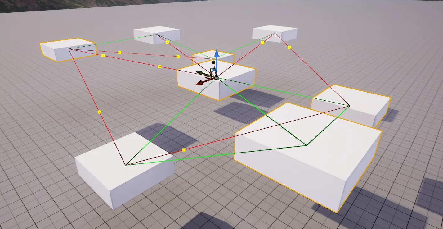
- The full example keys off that: it draws lines from the component’s owner to its linked actors and turns the line red past the metrics distance, with a point marking where the limit falls.
What this doesn’t cover
I covered drawing, not editing. The interactive side ( hit proxies, and handling mouse and key input so you can grab and drag a visualized handle the way the spline component lets you move its points ) is a separate set of overrides I didn’t get into here. The Limitations section above is the other half: when a visualizer is the wrong tool and what to reach for instead.